Riverside / UK
Riverside / UK
Riverside Resource Recovery Facility – A Successful Integrated Waste Management Solution for London

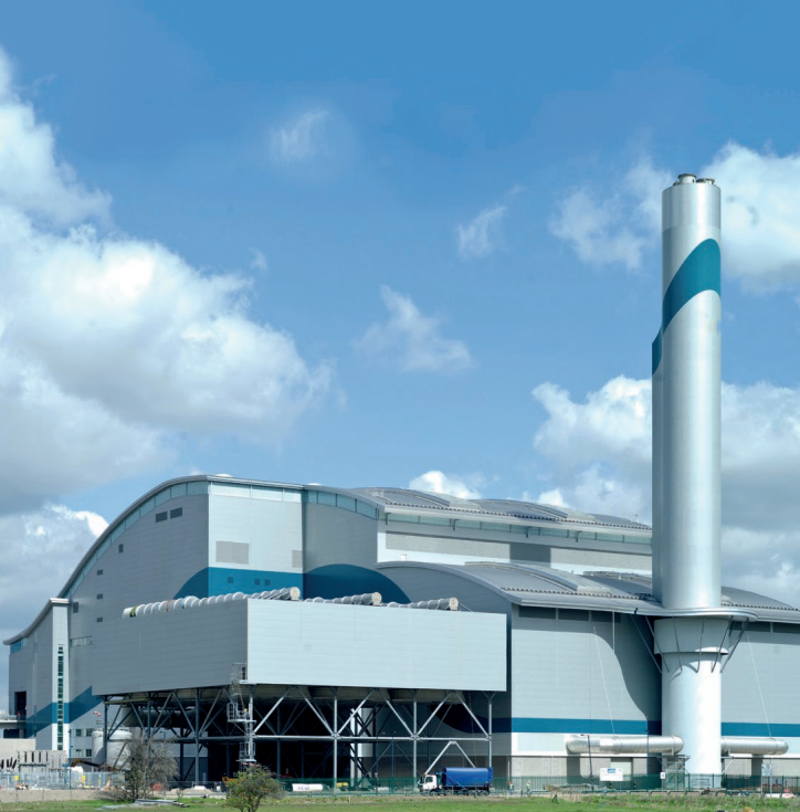
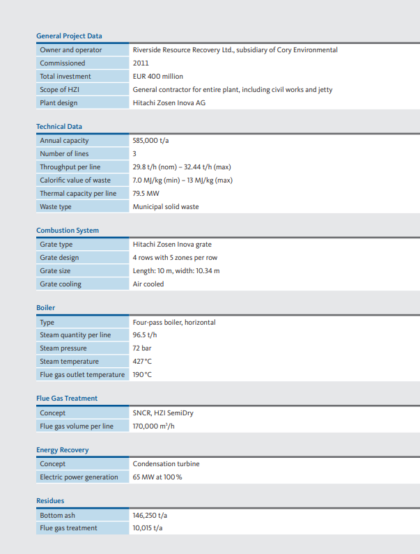
With an annual capacity of 585,000 tonnes, the Riverside Waste to Energy plant is an important strategic river-served waste management facility for London. It helps the capital to manage its own waste, keeping over 100,000 HGVs off congested roads and makes a real contribution to the city’s ability to meet its landfill diversion targets while producing electricity for more than 66,000 homes.
The project has successfully been developed by Cory Environmental after achieving planning in 2006 followed by a two-stage tender process, which Kanadevia Inova could secure in early 2007. The second stage consisted of an open book tender process for the civil works in cooperation with the client. The facility is owned and operated by Riverside Resource Recovery Ltd, a subsidiary of Cory Environmental. Kanadevia Inova has assumed in the role of an EPC contractor. Moreover O&M services are part of Kanadevia Inova’s delivery, which gave funders comfort with regard to a safe start-up of the plant and a smooth continuation into the operational phase.
Renewable Energy for UK’s Capital
As with Kanadevia Inova’s references in Paris, Oslo and Dublin, the Riverside Waste to Energy facility is another example of an energy recovery concept in one of the major capitals in Europe. The project proves today’s careful consideration with regard to integration and environmentally friendly concepts, not only through safe operation but also security in fulfilment of emissions legislation. Moreover, the focus is energy recovery. With a net electrical efficiency of over 27% the Riverside facility is among Europe’s most efficient Waste to Energy plants. Since the plant is located in a developing area, the water steam cycle of the facility was designed for future possible heat off-take for local district heating schemes. The Kanadevia Inova expertise with such highly complex process designs was a key factor for its selection as EPC contractor.
The Technical Set-Up for Safe and Economical Energy Recovery
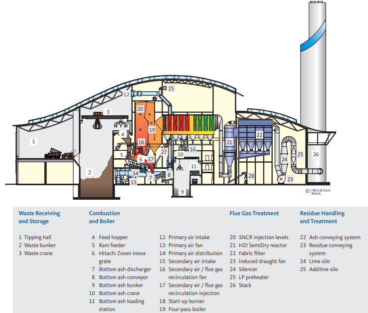
After various materials have been separated in a local material recycling facility via kerbside recycling schemes and the network of household waste recycling Sites, the residual waste is transported to the plant. Only 15% of the waste are delivered to the site directly by lorries. The remaining 85% of the waste is brought to the site by barges. At the jetty, the containers are unloaded onto vehicles, which will then tip-off the residual waste into a bunker within the waste reception hall. There the waste is thoroughly mixed by a crane and then fed into one of the feed hoppers. Each line has a four-pass boiler with a thermal capacity of 79.5 MW. The waste passes down a feed hopper chute onto the four-row Kanadevia Inova grate. The moving grate mixes and agitates the waste to allow an optimal burnout of the diverse waste fractions. In addition to this, a fully integrated control system allows for continuous adjustments of combustion conditions for the safest and most efficient operation possible. The process reduces the waste volume received by up to 90%. The burnt out ash passes through the ash discharger onto an ash handling system. The bottom ash is loaded into special containers, which will be further transported by barges, using the same system of water transport as the waste when being delivered to the facility. All these processes take place within enclosed areas. The bottom ash is sent for processing and reuse within the construction industry, for cover material or for disposal. By means of a metal separation process, ferrous and nonferrous material is also gained for recycling purposes.
Pyrolytic gas produced in the combustion process is mixed with secondary air and recirculated flue gas, which are injected tangentially at high velocity into the secondary combustion chamber above the grate, resulting in intensive mixing and the complete burnout of the pyrolytic gas. This is a first step in reducing emission levels. In parallel, the NOx-levels are maintained by means of Selective Non-Catalytic Reduction. The raw gas then passes through a water tube boiler where it is cooled while the water of the closed water steam cycle is superheated.
The superheated steam is then expanded by means of a turbo generator. As a result, electricity is produced to supply the facility thereby allowing the export for over 90% of the produced energy to the national grid. The energy recovery concept of the facility is also designed for potential off-take of steam or hot water for district heating purposes for future developments. After leaving the horizontal last pass of the boiler and having extracted as much energy as possible by still maintaining sufficient temperature levels for efficient and reliable removal of pollutents, the cleaning takes place in the SemiDry system consisting of a reactor in combination with a fabric filter. The well proven Kanadevia Inova SemiDry system keeps the plant in safe compliance with the emission limits of the European Union by operating below them. As reagents lime and activated carbon are used for the removal of gaseous pollutants, including heavy metals and dioxins. Small particles are separated in the fabric filter. The facility is also prepared to be operated with bicarbonate as the reagent in the event that this would prove to be suitable in the future. The residues resulting from the flue gas treatment are then either recycled (in the case of bicarbonate) or sent for safe disposal by an appropriate facility. The cleaned flue gas is finally released through the stack.

